Hey everyone, let’s talk about something that’s been coming up a TON lately for our Aluminum PCB customers—vibration. I get it, if you’re designing gear that’s meant to move, or hang out in a rough environment, you’re probably wondering: will this aluminum board hold up when things are shaking? Spoiler alert—this is a big deal, and it’s not just a “yes or no” question. Let’s break this down like we’re grabbing coffee and geeking out over circuit boards, no stuffy textbook jargon, promise. Aluminum PCB
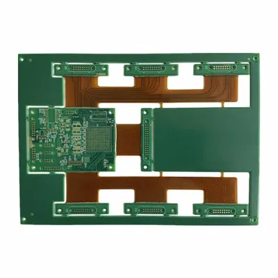
First, let’s get one tiny thing straight: when I say Aluminum PCB, I’m not talking about a regular flimsy fiberglass board with a layer of aluminum glued on the side. Nah, ours are built different. We start with a solid aluminum core—usually 1mm to 3mm thick, depending on what the customer needs—then there’s a dielectric layer (super important, it keeps the copper traces from touching the aluminum, don’t skip that part), then the actual copper circuit. That core is what makes these boards awesome for heat, but also what changes how vibration hits them.
So how does vibration even affect electronics in general? Vibration is just movement, right—constant back-and-forth, or up-and-down, sometimes at high speeds, sometimes low, and if there’s a lot of it, parts start to flex, or twist, or knock against each other. For regular FR-4 PCBs, you’ll usually see cracks in the copper traces if the flex is too much, or the whole board might delaminate from the solder pads. But aluminum PCBs? They’re stiffer, right? Aluminum is way harder than fiberglass. But that stiffness isn’t all good. It’s like a diving board—if it’s super thick and stiff, it doesn’t flex much at all, which means the force from vibration transfers straight through to the parts on it. Wait, that’s the key thing people miss. It’s not just “aluminum is stiff, so it doesn’t break”—it’s about how that stiffness interacts with the other layers, and the components you solder on.
Let’s get real with examples, because that’s what matters. Take a customer who makes outdoor LED street lights. Those things shake all the time—from wind gusts, traffic rumbling below, even the street maintenance trucks driving by. If they used a regular FR-4 board, the heat from the LEDs would build up and kill them way faster, so they switch to aluminum PCB. But a few years back, one of our clients told us their first batch kept failing after 6 months—traces cracked where they connected to the LED. Why? Because they used a thin aluminum core (1mm) with a super thin dielectric, and the LEDs were big, heavy modules. The vibration wasn’t flexing the board much, but the stress was concentrated right where the big component soldered down. The aluminum core didn’t give, so all that vibration force stayed at the pad.
We fixed that for them. We bumped up the core to 2mm, and used a slightly thicker dielectric (still thermally conductive, don’t worry—we use high-quality ceramic-filled dielectric that doesn’t kill heat transfer) which gave just a tiny bit of “give” at the component interface. Now their boards last 3x longer, no issues. That’s the thing with aluminum PCBs and vibration—it’s all about matching the core thickness, dielectric, and even the trace thickness to the application, not just grabbing whatever’s cheapest.
Wait, let’s talk about failure modes specific to aluminum PCBs, because that’s way more useful than general electronics stuff. First, trace cracking, which I just mentioned. But why is that different than FR-4? Because the coefficient of thermal expansion (CTE) is different. CTE is how much a material expands when it gets hot. Aluminum has a CTE of about 23 ppm/°C, while copper is around 17 ppm/°C. Wait, FR-4 is like 10-15 ppm, so that’s closer? But aluminum is way stiffer, so when vibration hits, the CTE mismatch (even with the small difference) creates stress that doesn’t get absorbed by flex. If you have a thin trace, especially under a big SMD component, that stress will make the tiny copper line crack right at the pad. We’ve seen this a lot with high-power devices—like MOSFETs, or power LEDs—they put a ton of heat, so the CTE shift between the aluminum core and copper is worse, plus the vibration is constant from the device operating.
Another failure mode? Delamination between the aluminum core and dielectric. Wait, that’s less common with good manufacturing, but vibration will make it worse if the bond is bad. If the dielectric isn’t bonded properly to the aluminum (we do plasma treatment on the core before applying dielectric, that’s our little trick), then vibration will cause tiny gaps to form at the interface, which kills heat transfer, and eventually the whole dielectric layer can lift. We had a customer a while back who tried to source aluminum PCBs from a cheap shop overseas—they skipped the plasma treatment, so after a month in vibrating heavy equipment, the dielectric peeled off. Lesson there: don’t cut corners on the prep work for the core if your application has vibration.
Third one is component lift-off or solder joint failure. This is huge. If you have a through-hole component—like a connector, or a big resistor that goes all the way through the board—vibration will shake the pins back and forth. On an FR-4 board, the board flexes, so the pins move with it, and the solder joint holds. But on aluminum, if the core is too thick, it barely flexes, so the pins are moving at one end (the component side) and the board is not moving at the other (the solder side). That’s pulling stress on the solder joint, and over time, it cracks, and the component stops working. We had a customer who made industrial control panels—they had a bunch of terminal blocks on their boards, and the solder joints kept breaking when the panels were mounted on factory walls (constant machinery vibration). We switched them to our 3mm thick core, and also added little strain relief pads around the terminal pins on the copper side—extra small copper lines that act like a buffer. Now those joints have lasted 2 years, no failures.
Wait, but not all vibration is bad. Wait, no—all vibration is stress, but aluminum PCBs have a big upside here too that a lot of people don’t talk about. The heat dissipation. If your board is in an environment that’s both hot and vibrating, the aluminum core’s ability to pull heat away from components means less thermal expansion overall. Remember that CTE mismatch I was talking about? If the whole board runs cooler, the materials expand less, so the stress from vibration is way lower. That’s a double win, right? The core reason people use aluminum PCBs is heat, and that same property reduces the stress that causes vibration failure. For example, in electric vehicle battery management systems (BMS), those boards have to handle high heat from the battery cells, and constant vibration from driving down bumpy roads. Aluminum PCB is perfect here because it keeps the BMS cool, so less expansion, and the vibration that is there is spread out more because the heat is being managed. We’ve worked with a few EV component makers, and their FR-4 BMS boards would fail vibration testing at 2g (that’s the standard automotive vibration test, by the way) but our aluminum ones pass easily, no issues.
Now, what can you, the designer, do to make sure your aluminum PCB works with vibration? Let’s get into actionable stuff, not just theory. First, match core thickness to your component size. If you’re using small 0402 SMD components, 1mm or 1.5mm core is fine—they don’t put a lot of stress. If you’re using big 2W+ power LEDs, or through-hole connectors, go for 2mm or 3mm. It’s a tiny cost difference, but it makes a huge difference in durability. Second, use a thermally conductive dielectric with slightly more flexibility. We don’t use super brittle dielectric because it’s better for heat, we use a ceramic-filled type that has a little give, so it can absorb some of the stress instead of transferring it straight to the copper. Third, add strain relief at component pads—little copper traces or teardrops on the SMD pads, or even small copper “arms” around through-hole pins. That’s a trick we’ve refined over the years, and it’s saved so many of our customers from failure. Fourth, test for resonance. Wait, resonance is when the board vibrates at its natural frequency, which amplifies the movement way more than regular vibration. If you design a board with a big empty section in the middle, that section will vibrate at a certain frequency, and if that matches the frequency of your application (like a motor running at 50Hz), you’re going to have a bad time. We help our customers with this—we do finite element analysis (FEA) for free on all our custom boards, to check for resonance before we even fabricate. That’s a service a lot of suppliers don’t offer, but it’s critical for vibration-heavy applications.
Let’s be real, there are myths out there too. Some designers think “aluminum is rigid, so it’s always better for vibration.” No. If you use a too-thick core, you get more stress on the solder joints, like that terminal block example I had. Others think “dielectric doesn’t matter for vibration.” Also wrong—bad dielectric bond = delamination. And some think “only big, heavy components have issues with vibration.” Nope, even tiny ones—if you have a bunch of 0201 resistors packed tight, the constant vibration can make their tiny solder balls crack if the board is too stiff, because there’s no room for the board to flex a little instead of putting all stress on the tiny joint.
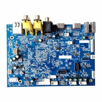
Wait, let’s wrap this up with a real example that’s fresh. Last quarter, we worked with a company that makes portable industrial monitors—you know, the ones factory workers carry around, bump into things, drop occasionally, and use 8 hours a day on a vibrating assembly line. They originally used FR-4 boards, and their failure rate was 12% after 3 months—mostly broken solder joints on the main processor. They switched to our aluminum PCB, and we did two things: we used a 2mm aluminum core, and we added a custom strain relief zone around the processor pad, with extra copper traces that spread out the stress. Now their failure rate is less than 1% after 6 months, and they’ve re-ordered 3 times. That’s the proof, right? It’s not just “aluminum works with vibration” — it’s “aluminum works when you design it right for vibration, matching the core, layers, and layout to your specific use case.”
Quick Turn PCB Assembly If you’re reading this, and you’re designing something that’s going to be in a vibrating environment—industrial equipment, LED lighting, automotive parts, portable electronics, whatever—don’t gamble on a random supplier off Alibaba. We’ve been doing aluminum PCBs for over 10 years, we’ve fixed more vibration-related failures than I can count, and we’ll walk through every step with you. If you’re tired of boards breaking when they shake, or overheating, hit us up for a custom quote. No pressure, no weird fine print, just solid advice and boards that actually work.
References
- Tummala, R. R. (2016). Fundamentals of Microsystems Packaging. McGraw-Hill Education.
- Liu, Y., et al. (2020). Vibration-induced failure analysis of high-power aluminum PCB assemblies for automotive applications. IEEE Transactions on Components, Packaging and Manufacturing Technology, 10(9), 1521-1528.
- Zhang, H., et al. (2018). Effect of core thickness on mechanical and thermal performance of aluminum printed circuit boards under cyclic vibration loading. Journal of Electronic Materials, 47(12), 7219-7227.
- IPC-2221A. (2018). Generic Standard on Printed Board Design. IPC Association Connecting Electronics Industries.
Huaswin Electronics Technology Co., Ltd.
Address: Building A2, Hao Hai Hong Industrial Park, No.3 Yu He Road, Gong He, Sha Jing, Bao An, Shenzhen
E-mail: sales@huaswin.com
WebSite: https://www.huaswin-pcba.com/
