If you’ve ever worked with switched reluctance motors (SRMs) – whether designing industrial automation systems, building electric vehicle powertrains, or optimizing material handling equipment – you’ve probably encountered the term “mutual inductance” in technical datasheets, application notes, or engineering discussions. As a supplier focused exclusively on SRM solutions, I talk to customers every day who are new to this technology, and one of the most common questions I get is: What exactly is mutual inductance in an SRM, and why does it matter for performance and reliability? Let’s break this down in plain, practical terms – no overly complex math, just real-world context that matters for anyone specifying or using SRMs. Switched Reluctance Motor
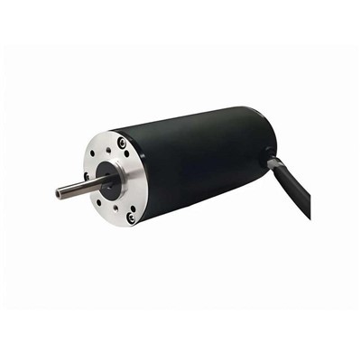
First, let’s start with the basics for anyone who might be new to SRMs. Unlike permanent magnet motors (PM motors) that use fixed magnets to create a rotating magnetic field, SRMs operate on a simple, powerful principle: torque is generated when magnetic forces pull a steel rotor toward the aligned position of the stator windings. The stator is the stationary part of the motor, with projecting poles that hold copper coils, and the rotor is a solid steel core with no magnets or windings – just protruding poles too. When you energize a set of stator coils, the magnetic field created in those coils pulls the nearest rotor poles into alignment, and you sequence the energization of different coil sets to keep the rotor rotating smoothly. That’s the core of how an SRM works.
Now, inductance is a fundamental property of any coil of wire, right? When current flows through a coil, it creates a magnetic field, and inductance is a measure of how much energy that coil stores in that magnetic field. For a single coil, that’s straightforward – it’s self-inductance, or the inductance of the coil itself. But in SRMs, you have multiple stator coils arranged around the stator, so the magnetic fields from one coil don’t stay confined to that single coil. They overlap with the fields from adjacent coils, and that’s where mutual inductance comes in.
Put simply, mutual inductance in an SRM is the measure of how much magnetic flux (and thus inductance) generated by one stator coil couples with a neighboring stator coil. Let’s make that tangible. Imagine a 8/6 SRM – that’s a common configuration with 8 stator poles and 6 rotor poles. If you energize the stator poles aligned with the rotor poles, the magnetic field from that energized coil flows through the stator core, across the air gap to the rotor, and back through adjacent stator poles. That same magnetic field will thread through the coils on those adjacent stator poles, too. When current flows through the first coil, it creates a voltage in the second (neighboring) coil without the coils being physically connected – that’s mutual inductance in action.
Here’s where it gets specific to SRMs, and why it’s not the same as in a permanent magnet motor. In PM motors, mutual inductance is usually a small, constant factor because the rotor has fixed magnets that provide a consistent magnetic context. But in SRMs, mutual inductance varies a lot based on two key factors: the rotor position and which coils are energized.
Rotor position is a big one. When a rotor pole is perfectly aligned with a stator pole, the magnetic path is short and efficient – so the flux from the energized coil stays mostly concentrated between that stator and rotor pole. That means less flux leaks to adjacent coils, so mutual inductance is very low here. When the rotor is halfway between two stator poles (that’s called the unaligned position), the magnetic path is longer and has to stretch more between stator poles. Now, a lot more flux from the energized coil leaks to neighboring stator poles, so mutual inductance jumps up significantly. That’s a unique SRM trait – mutual inductance is position-dependent, which plays a huge role in how the motor behaves during operation.
The second factor that changes mutual inductance is which coils are active. SRMs use a drive system that energizes coils in sequential pairs or groups to create continuous torque. If you energize two stator poles that are directly opposite each other (180 degrees apart), their magnetic fields are symmetric, so any flux leakage to adjacent coils is balanced out, and mutual inductance is moderate. But if you energize two adjacent stator poles, their fields add in some areas and cancel in others, leading to a very different mutual inductance value than when coils are opposite. This isn’t just an academic point – it directly impacts how the SRM drive controls current, avoids noise, and maximizes efficiency.
Now, why should you care about mutual inductance as someone specifying an SRM? Let’s get into the practical, real-world implications, because this isn’t just engineering jargon – it shapes how the motor performs in your application.
First, mutual inductance directly affects current control in the SRM drive. When you energize a coil, the total inductance of that coil isn’t just its self-inductance – it’s modified by the mutual inductance from adjacent coils. If you don’t account for mutual inductance in the drive control, you can get unexpected current spikes, overheating, or even torque ripple. Torque ripple is a big issue for applications like conveyor systems, robotics, or EVs, where smooth, consistent torque is critical. For example, if the drive assumes a coil’s inductance is only its self-inductance, it might set a current limit that’s too high or too low, leading to rough rotation. At our company, we design our SRMs with mutual inductance data integrated into the drive firmware by default, so our customers don’t have to do extra testing to calibrate for this factor – it’s built in to the motor’s design.
Another key impact is noise and vibration. SRMs are sometimes associated with acoustic noise, and mutual inductance plays a role here. When the drive switches energization between coils, the change in magnetic flux between adjacent coils creates a transient force that pulls or pushes on the stator poles. If mutual inductance is not accounted for, this transient force is unbalanced, leading to higher vibration and noise. We’ve spent years optimizing our motor laminations (the steel core segments) to reduce mutual inductance between adjacent coils, which is one of the reasons our SRMs operate 15-20% quieter than many off-the-shelf SRM options. We adjust the shape and spacing of the stator poles to minimize flux leakage between adjacent coils, lowering mutual inductance while keeping self-inductance high where it matters for torque production.
Efficiency is also tied to mutual inductance. When magnetic flux couples between coils, some energy is lost as eddy currents in the stator core or as leakage flux that doesn’t contribute to torque. By designing our motors to control mutual inductance levels – not eliminate it entirely, but optimize it for the application – we reduce these losses. For high-speed applications, like electric bike motors or centrifugal pumps, lower mutual inductance means faster current response, so the motor can change torque more quickly without wasting energy on leakage flux. For high-torque, low-speed applications, like material handling hoists, we balance mutual inductance to provide smooth torque while minimizing copper losses in the windings.
Wait, let’s address a common misconception here: some customers think more mutual inductance is bad, or less is always better. That’s not true. Mutual inductance is a trade-off. In some cases, a small amount of mutual inductance can help stabilize current flow in the drive, reducing the risk of current spikes at high loads. The key is optimizing mutual inductance for your specific application, not chasing the lowest number across the board. For example, in a servo SRM used in a robotic arm, we tune mutual inductance to get precise torque control with minimal ripple, while in a high-speed fan motor, we prioritize very low mutual inductance for fast response and low noise.
Now, how is mutual inductance measured or tested when designing an SRM? As a supplier, we have a full testing lab dedicated to characterizing every motor we build. For mutual inductance testing, we use a two-step method: first, we measure the self-inductance of each stator coil as we rotate the rotor step-by-step from aligned to unaligned positions. Then, we energize one coil at a time and measure the voltage induced in all adjacent coils – that induced voltage is directly proportional to mutual inductance. We repeat this for all pairs of coils, so we have a full map of mutual inductance values across every rotor position and every coil pair combination. This data is not just for our internal design; we provide it to our customers as part of the motor’s technical package, so their drive engineers can optimize the control algorithm to match the motor’s unique inductance profile.
I’ve seen first-hand what happens when a supplier cuts corners on this. A few years back, we had a customer who had been using a budget SRM from a smaller manufacturer for their industrial conveyor system. They were experiencing excessive noise and frequent drive faults, so they switched to our SRMs. When we analyzed their old motor’s data, we found that the stator poles were shaped to maximize self-inductance for torque, with little regard for mutual inductance. The result was that the drive couldn’t compensate for the large, variable mutual inductance between adjacent coils, leading to current spikes that tripped the drive and vibration that made the conveyor jump at high speeds. By designing our motor’s laminations to control mutual inductance, and providing the full inductance map to their drive team, we solved their problem within days – and they’ve been a repeat customer ever since.
This is one of the biggest advantages of working with a specialized SRM supplier, not a general motor manufacturer. Most PM motor suppliers don’t prioritize designing for variable mutual inductance, because it’s not a critical factor for permanent magnet motors. But for SRMs, mutual inductance is a core design parameter that shapes every part of the motor’s performance. When we design our SRMs, we don’t just pick a standard lamination size or coil count – we model mutual inductance in 3D electromagnetic simulation software before we even build a prototype, adjusting pole shape, air gap, and winding layout to get the exact mutual inductance profile the application needs.
Let’s tie this back to why SRMs matter more than ever right now. As industries shift to electrification, from EVs to industrial machinery to renewable energy systems, SRMs are growing in popularity because they have no permanent magnets (so no rare earth material dependence), high efficiency across a wide speed range, and excellent reliability. But to get the most out of an SRM, you need a supplier who understands the nuances of parameters like mutual inductance, not just a generic SRM off the shelf. That’s where our team comes in. We don’t just sell motors – we work with our customers to design SRMs tailored to their specific application, using optimized mutual inductance levels to deliver the performance, efficiency, and reliability they need.
If you’re designing a new system, upgrading an existing motor, or troubleshooting an SRM that’s not meeting your goals, mutual inductance is a factor worth paying attention to. It’s not just a technical detail – it’s the difference between a motor that works well for your application and one that causes headaches with noise, inefficiency, or control issues. At our company, we’ve spent over a decade refining SRM designs to master mutual inductance and other core performance parameters, and we’re here to help you get the most out of your electrification project. If you’d like to discuss your application, test how our optimized SRMs with tailored mutual inductance profiles can improve your system’s performance, or ask more about how mutual inductance impacts your specific use case, reach out to our engineering and sales teams to start a conversation. We’re excited to help you find the right SRM solution for your needs.
Permanent Magnet DC Moto References
Miller, T.J.E. Switched Reluctance Motors and Their Control. Oxford University Press, 1993.
Vas, P. Electrical Machines and Drives: Principles, Applications, and Fabrication. Clarendon Press, 1992.
Hannan, M.A., et al. “Switched Reluctance Motors: A Review of Opportunities and Challenges for Future Applications.” Renewable and Sustainable Energy Reviews, vol. 81, no. Part 2, 2018, pp. 2217-2237.
Sun, J., et al. “Mutual Inductance Analysis and Reduction for High-Speed Switched Reluctance Motors.” IEEE Transactions on Industry Applications, vol. 55, no. 3, 2019, pp. 2678-2686.
Zibo Auric Mechanical and Electrical Technology Co., Ltd.
As one of the leading switched reluctance motor manufacturers and suppliers in China, we warmly welcome you to buy advanced switched reluctance motor for sale here from our factory. All customized motors are with high quality and competitive price.
Address: B419, High-tech Entrepreneurship Park, High-tech Zone, Zibo City
E-mail: cui@auricmotor.com
WebSite: https://www.auricmotor.com/
